CBSE Class 12 Physics Chapter 2 Extra Questions. We know Physics is tough subject within the consortium of science subjects physics is an important subject. But if you want to make career in these fields like IT Consultant, Lab Technician, Laser Engineer, Optical Engineer etc. You need to have strong fundamentals in physics to crack the exam. myCBSEguide has just released Chapter Wise Question Answers for class 12 Physics. There chapter wise Extra Questions with complete solutions are available for download in myCBSEguide website and mobile app. These Questions with solution are prepared by our team of expert teachers who are teaching grade in CBSE schools for years. There are around 4-5 set of solved Physics Extra Questions from each and every chapter. The students will not miss any concept in these Chapter wise question that are specially designed to tackle Board Exam. We have taken care of every single concept given in CBSE Class 12 Physics syllabus and questions are framed as per the latest marking scheme and blue print issued by CBSE for class 12.
Class 12 Physics Extra Questions
-
Correct formula for capacitance in terms of area A and distance d, of a parallel plate capacitor in vacuum is
- {tex}\epsilon_0\frac{A}{d^2}{/tex}
- {tex}\epsilon_0\frac{A^2}{d}{/tex}
- {tex}\epsilon_0\frac{d}{A}{/tex}
- {tex}\epsilon_0\frac{A}{d}{/tex}
-
Two parallel plate capacitors of capacitances C and 2C are connected in parallel and charged to a potential difference V by a battery. The battery is then disconnected and the space between the plates of capacitor C is completely filled with a material of dielectric constant K = 3. The potential difference across the capacitors now becomes
- {tex}{2V \over 5}{/tex}
- {tex}{3V \over 6}{/tex}
- {tex}{V \over 4}{/tex}
- {tex}{3V \over 5}{/tex}
-
A variable capacitor and an electroscope are connected in parallel to a battery. The reading of the electroscope would be decreased by
- Decreasing the battery potential
- Increasing the area of overlapping of the plates
- Decreasing the distance between the plates
- Placing a dielectric between the plates
- The capacity of a pure capacitor is 1 farad. In DC circuit its effective resistance will be
- infinite
- zero
- 1 {tex}\Omega {/tex}
- 2 ohm
-
In circuits, a difference in potential from one point to another is often called
- volts
- AT
- field
- voltage
-
What is the geometrical shape of equipotential surfaces due to a single isolated charge?
-
Draw equipotential surfaces due to a single point charge.
-
Two charges 2 µC and -2 µC are placed at points A and B, 5 cm apart. Depict an equipotential surface of the system.
-
What are the dimensions of capacitance?
-
A slab of material of dielectric constant K has the same area as that of the plates of a parallel plate capacitor, but has the thickness d/2, where d is the separation between the plates. Find out the expression for its capacitance when the slab is inserted between the plates of the capacitor.
-
Two capacitors of 1 µF capacitance are connected to a battery of 6 V. Initially switch S is closed. After sometime S is left open and dielectric slab of dielectric constant K = 3 are inserted to fill completely the space between the plates of the two capacitors.
How will the (i) charge and (ii) potential difference between the plates of the capacitors be affected after the slabs are inserted?

-
Electric charge is distributed uniformly on the surface of a spherical rubber balloon. Show how the value of electric intensity and potential vary
- on the surface,
- inside and
- outside?
-
A {tex}5\mu F{/tex} capacitor is charged by a 100 V supply. The supply is then disconnected and the charged capacitor is connected to another uncharged {tex}3\mu F{/tex} capacitor. How much electrostatic energy of the first capacitor is lost in the process of attaining the steady situation?
-
- Derive the expression for the capacitance of a parallel plate capacitor having plate area A and plate separation d.
- Two charged spherical conductors of radii R1 and R2 when connected by a conducting plate respectively. Find the ratio of their surface charge densities in terms of their radii.
-
- Explain using suitable diagrams, the difference in the behaviour of a
- conductor and
- dielectric in the presence of external electric field. Define the terms polarisation of a dielectric and write its relation with susceptibility.
- A thin metallic spherical shell of radius R carries a charge Q on its surface. A point charge Q/2 is placed at its centre C and another charge + 2Q is placed outside the shell at a distance x from the centre as shown in the figure. Find

- Explain using suitable diagrams, the difference in the behaviour of a
- the force on the charge at the centre of shell and at the point A,
- the electric flux through the shell.
Class – 12 Physics (Electrostatics Potential and Capacitance)
Answers
-
- {tex}\epsilon_0\frac{A}{d}{/tex}Explanation: The capacitance of a parallel plate capacitor is given by {tex}C = \frac{{{\varepsilon _0}A}}{d}{/tex}
- {tex}{3V \over 5}{/tex}Explanation: The charges on the capacitors after being charged to a potential V are Q1 = CV; Q2 = 2CV.
After being filled with a material of dielectric K = 3 the capacitor which initially had a capacitance C has now the capacitance KC = 3C. The common potential
{tex}{V_1} = \frac{{{\text{Total charge}}}}{{{\text{Total capacitance}}}} = \frac{{{Q_1} + {Q_2}}}{{3C + 2C}}{/tex}
{tex} = \frac{{CV + 2CV}}{{5C}} = \frac{3}{5}V{/tex}
- Decreasing the battery potential
Explanation: An electroscope is a device which measures the potential difference. If it is connected in parallel to the capacitor, the potential across it will be equal to the potential across the capacitor, which is equal to the potential across the battery. On decreasing the battery potential, the potential difference across the electroscope reduces and hence the reading reduces. While the capacitor is connected to the battery, Placing a dielectric between the plates, or decreasing the distance between the plates or increasing the area of the plates will not change the potential difference across it; since it will always remain equal to the potential difference maintained by the battery. In the cases B, C and D, The capacitance of the capacitor, however increases; but this increase happens due to increase in the charge stored in the capacitor while the potential remains constant.
- infinite
Explanation: Capacitor does not allow DC to pass through it. The effective capacitance or the capacitive reactance {tex}{X_C} = \frac{1}{{C\omega }}{/tex},
where ω is the frequency of voltage source.
Since DC current is a constant current, its frequency is zero.
The capacitive reactance is therefore infinity.
- voltage
Explanation: Voltage is an electrical potential difference, the difference in electric potential between two places. The unit for electrical potential difference, or voltage, is the volt.
- The equipotential surfaces produced by a single point charge are spherically symmetrical surfaces which are concentric.
In concentric spheres which are as shown below in the figure, the lines of force point radially outwards, so they are perpendicular to the equipotential surfaces at all points.
If we place another unit positive charge at any point on these surfaces, that will repelled along the the direction of the electric field intensity i.e. radially outwards to the surfaces.

- Equipotential surfaces due to a single point charge are concentric sphere having charge at the centre. Electric field lines are always normally outwards from the spherical surfaces.

- Given, {tex}q _ { A } = 2 \mu C = 2 \times 10 ^ { – 6 } C{/tex}
{tex}q _ { g } = – 2 \mu C = – 2 \times 10 ^ { – 6 } C{/tex} and r = 5 cm
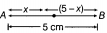
As, potential at point O is zero.
{tex}V = \frac { 2 \times 10 ^ { – 6 } } { 4 \pi \varepsilon _ { 0 } x \times 10 ^ { – 2 } } + \frac { – 2 \times 10 ^ { – 6 } } { 4 \pi \varepsilon _ { 0 } ( 5 – x ) \times 10 ^ { – 2 } } = 0{/tex}
or {tex}\frac { 2 \times 10 ^ { – 6 } } { 4 \pi \varepsilon _ { 0 } x \times 10 ^ { – 2 } } = \frac { 2 \times 10 ^ { – 6 } } { 4 \pi \varepsilon _ { 0 } ( 5 – x ) \times 10 ^ { – 2 } }{/tex}
or x = 5 – x {tex}\Rightarrow{/tex} x = 2.5 cm
Hence equipotential surface is a plane normal to the axis of the dipole and lies at the mid point of the axis. - {tex}\left[ {{M^{ – 1}}{L^{ – 2}}{A^2}{T^4}} \right]{/tex}
- Initially, when there is vacuum between the two plates of the capacitor, then capacitance of the capacitor becomes {tex}C _ { 0 } = \frac { \varepsilon _ { 0 } A } { d }{/tex},
where, A is the area of each plate of the capacitor.
Suppose that the capacitor is connected to a battery, an electric field E0 is produced.
Now, if we insert the dielectric slab of dielectric constant K and of thickness t = d/2, the electric field reduces to E = E0/K.
Now, the gap between plates is divided in two parts, for distance t, there is electric field E and for the remaining distance (d – t) the electric field is E0.
If V be the potential difference between the plates of the capacitor after inserting the dielectric slab, then V = Et + E0(d – t)
{tex}\Rightarrow V = \frac { E d } { 2 } + \frac { E _ { 0 } d } { 2 } = \frac { d } { 2 } \left( E + E _ { 0 } \right) \quad \left[ \because t = \frac { d } { 2 } \right]{/tex}
{tex}\Rightarrow \quad V = \frac { d } { 2 } \left( \frac { E _ { 0 } } { K } + E _ { 0 } \right){/tex}
{tex}= \frac { d E _ { 0 } } { 2 K } ( K + 1 ){/tex} {tex}\left[ \text { As, } \frac { E _ { 0 } } { E } = K \right]{/tex}
Now, {tex}E _ { 0 } = \frac { \sigma } { \varepsilon _ { 0 } } = \frac { q } { \varepsilon _ { 0 } A } {/tex}, Hence the potential becomes {tex} V = \frac { d } { 2 K } \cdot \frac { q } { \varepsilon _ { 0 } A } ( K + 1 ){/tex}
Again we know that, {tex}C = \frac { q } { V } = \frac { 2 K \varepsilon _ { 0 } A } { d ( K + 1 ) }{/tex}(substituting the value of V)- According to the diagram, when the switch S is closed, the two capacitors C1 and C2 in parallel will be charged by the same potential difference V.

So, charge on capacitor C1{tex}q _ { 1 } = C _ { 1 } V = 1 \times 6 = 6 \mu \mathrm { C }{/tex} ….(i)
and charge on capacitor C2
{tex}q _ { 2 } = C _ { 2 } V = 1 \times 6 = 6 \mu C{/tex} …(ii)
Hence total charge, q = q1 + q2 = 6 + 6 = 12µC (before the switch S is closed) Now when S is left open, there will be no change in the stored charge value of C2 and the change in charge value in C1 is given in the answer (ii). - When switch S is opened and dielectric is introduced. Then

Capacity of both the capacitors becomes K times
i.e. {tex}C’ _ { 1 } = C _ { 2 } ^ { \prime } = K C = 3 \times 1 = 3 \mu F \left( \operatorname { as } C _ { 1 } ^ { \prime } = C’ _ { 2 } \right){/tex}
Capacitor A remains connected to battery
{tex}\therefore \quad V _ { 1 } ^ { \prime } = V = 6 \mathrm { V }{/tex}
{tex}q _ { 1 } ^ { \prime } = K q _ { 1 } = 3 \times 6 \mu C = 18 \mu C{/tex} (charge in C1 is increased to 3 times of the previous value)
Capacitor B becomes isolated, charge in it will remain same
{tex}\therefore q’ _ { 2 } = q _ { 2 } ~{ \Rightarrow } ~C’ _ { 2 } V’ _ { 2 } = C _ { 2 } V _ { 2 }{/tex} or {tex}( K C ) V’ _ { 2 } = C V{/tex} (C2 = C, C’2 = KC)
or {tex}V _ { 2 } = \left( \frac { V } { K } \right) = \frac { 6 } { 3 } = 2 V{/tex} (potential difference of the capacitor B is reduced to a factor of 3)
- According to the diagram, when the switch S is closed, the two capacitors C1 and C2 in parallel will be charged by the same potential difference V.
- On the surface E = constant, V = constant. Inside the surface, E = 0, V = constant = potential on surface. Outside the balloon.
{tex}E \propto \frac{1}{{{r^2}}}{/tex} and {tex}V \propto \frac{1}{r}{/tex}
where r is the distance of the point from the centre of the balloon. - Initial energy stored in {tex}5\mu F{/tex} capacitor,
{tex}{U_i} = \frac{1}{2}C{V^2} = \frac{1}{2} \times 5 \times {10^{ – 6}} \times {(100)^2}{/tex}
{tex} = 2.5 \times {10^{ – 2}}J{/tex}
Charge on 5 mF capacitor {tex} = 5 \times {10^{ – 6}} \times 100{/tex}
{tex} = 5 \times {10^{ – 4}}C\left[ {\because q = CV} \right]{/tex}
The two capacitors attain a common potential V when they are connected together.
{tex}V = \frac{{Total\;ch\arg e}}{{total\;capacitor}} = \frac{{5 \times {{10}^{ – 4}}}}{{(5 + 3) \times {{10}^{ – 6}}}} = \frac{{125}}{2}V{/tex}
Final energy of the combination,
{tex}{U_f} = \frac{1}{2} \times (5 + 3) \times {10^{ – 6}} \times {\left( {\frac{{125}}{2}} \right)^2} = 1.56 \times {10^{ – 2}}J{/tex}
Electrostatic energy lost in the process of attaining the steady state
{tex} = {U_i} – {U_f} = (2.5 – 1.56) \times {10^{ – 2}}{/tex}
{tex} = 0.94 \times {10^{ – 2}}J{/tex}- Parallel plate capacitor consists of two thin conducting plates each of area A held parallel to each other at a suitable distance d. One of the plates is insulated and other is earthed. Say, there is vacuum or air between the plates. Structure of a parallel plate capacitor is shown below.

Suppose, the plate X is given a charge of +q coulomb. By induction, -q coulomb of charge is produced on the inner surface of the plate Y and +q coulomb on the outer surface. Since, the plate Y is connected to the earth, hence the relatively weak charge +q residing far away i.e. on the outer surface flows to the earth. Thus, the plates X and Y have equal and opposite charges +q and -q respectively
Suppose, the surface density of charge on each plate is {tex}\sigma{/tex}, We know that the intensity of electric field at a point between two plane parallel sheets of equal and opposite charges is = {tex}\frac {\sigma }{2 \epsilon _0} -(-\frac {\sigma }{2\epsilon _0}) ={/tex} {tex}\sigma/\varepsilon_0{/tex} [{tex}\frac {+ \sigma}{2\epsilon _0} ~and ~ \frac {- \sigma}{2 \epsilon_0}{/tex} are electric field intensities in between the two plates due to charges +q and -q on the two plates of the capacitor respectively], where {tex}\varepsilon_0{/tex} is the permittivity of free space. The intensity of electric field between the plates will be given by, {tex}E = \frac { \sigma } { \varepsilon _ { 0 } }{/tex}
The charge on each plate is q and the area of each plate is A. Thus,
{tex}\sigma = \frac { q } { A } \text { and } E = \frac { q } { \varepsilon _ { 0 } A }{/tex}…………(i)
Now, let the potential difference between the two plates be V volt. Then, the electric field between the plates is given by
{tex}E = \frac { V } { d } \quad \text { or } \quad V = E d{/tex}…..(ii)
Substituting the value of E from equation (i) into equation (ii), we get
{tex}V = \frac { q d } { \varepsilon _ { 0 } A }{/tex}
Now capacitance of the parallel plate capacitor is
{tex}C = \frac { q } { V } = \frac { q } { q d / \varepsilon _ { 0 } A } \quad \text { or } \quad C = \frac { \varepsilon _ { 0 } A } { d }{/tex}
Where, {tex}\varepsilon _ { 0 } = 8.85 \times 10 ^ { – 12 } \mathrm { C } ^ { 2 } – \mathrm { Nm } ^ { – 2 }{/tex} is the permittivity of vacuum or air. - Surface charge density of a spherically charged body is given by
{tex}\sigma = \frac { q } { 4 \pi R ^ { 2 } }{/tex}
After connecting both the conductors, their potentials will become equal.
{tex}\Rightarrow \frac { K q _ { 1 } } { R _ { \mathrm { l } } } = \frac { K q _ { 2 } } { R _ { 2 } }{/tex} [ For a spherically charged conductor with charge q potential is given by, {tex}V = \frac { 1 } { 4 \pi \varepsilon _ { 0 } } \frac { q } { R } \text { or } V = \frac { K q } { R }{/tex}] {tex}\therefore \frac { q _ { 1 } } { q _ { 2 } } = \frac { R _ { 1 } } { R _ { 2 } } ~Hence~ \frac { \sigma _ { 1 } } { \sigma _ { 2 } } = \frac { q _ { 1 } / 4 \pi R _ { 1 } ^ { 2 } } { q _ { 2 } / 4 \pi R _ { 2 } ^ { 2 } }{/tex}
{tex}= \frac { q _ { 1 } } { q _ { 2 } } \left( \frac { R _ { 2 } } { R _ { 1 } } \right) ^ { 2 } = \frac {R_1}{R_2}× \left (\frac {R_2}{R_1} \right)^{2}= \frac { R _ { 2 } } { R _ { 1 } }{/tex}
-
- When a conductor is placed in an external electric field, the free charges present inside the conductor redistribute themselves in such a manner that the electric field due to induced charges opposes the external field within the conductor. This happens until a static situation is achieved, i.e. when the two fields cancels each other, then the net electrostatic field in the conductor becomes zero.
- Dielectrics are non-conducting substances. i.e. they have no charge carriers. Thus, in a dielectric, free movement of charges is not possible. When a dielectric is placed in an external electric field, the molecules are re-oriented and thus induces a net dipole moment in the dielectric. This produces an electric field. The diagram clearly shows that the net electric field in case of a conductor becomes zero, whereas in case of a dielectric net electric field intensity becomes non zero.

However, the opposing field is so induced that does not exactly cancel the external field. It only reduces it. And the resultant electric field reduces by some value.
Both polar and non-polar dielectric develop net dipole moment in the presence of an external field. The dipole moment per unit volume of the substance is called polarisation and is denoted by P for linear isotropic dielectrics. {tex}P = \chi E{/tex}, {tex}\chi {/tex} is the susceptibility.
- At point C, inside the shell. The electric field inside a spherical shell is zero. Thus, the force experienced by the charge Q/2 kept at the centre C of the shell will also be zero.
{tex}\because F _ { C } = q E \quad \left( E _ { \text { nside the shell } } = 0\right.{/tex})
{tex}\therefore F _ { C } = 0{/tex}
At point ‘A’, magnitude of the force experienced by charge +2Q there, IFA= 2Q × {tex}\left( \frac { 1 } { 4 \pi \varepsilon _ { 0 } } \frac { 3 Q / 2 } { x ^ { 2 } } \right){/tex} (since 3Q/2 is the net charge of the shell)
{tex}\therefore F = \frac { 3 Q ^ { 2 } } { 4 \pi \varepsilon _ { 0 } x ^ { 2 } }{/tex} , direction of this force is away from shell - Electric flux through the shell, {tex}\phi = \frac { 1 } { \varepsilon _ { 0 } } {/tex} × magnitude of the net charge enclosed by the shell. (In this case there is no effect of the charge which lies above the shell)
{tex}\Rightarrow \quad \phi = 1 / \varepsilon _ { 0 } \times Q / 2 = Q / 2 \varepsilon _ { 0 }{/tex}
- Parallel plate capacitor consists of two thin conducting plates each of area A held parallel to each other at a suitable distance d. One of the plates is insulated and other is earthed. Say, there is vacuum or air between the plates. Structure of a parallel plate capacitor is shown below.
Chapter Wise Extra Questions of Class 12 Physics Part I & Part II
- Electric Charges and Fields
- Electrostatic Potential and Capacitance
- Current Electricity
- Moving Charges and Magnetism
- Magnetism and Matter
- Electromagnetic Induction
- Alternating Current
- Electromagnetic Waves
- Ray Optics and Optical
- Wave Optics
- Dual Nature of Radiation and Matter
- Atoms
- Nuclei
- Electronic Devices
Test Generator
Create question paper PDF and online tests with your own name & logo in minutes.
Create Now
Learn8 App
Practice unlimited questions for Entrance tests & government job exams at ₹99 only
Install Now