
Ask questions which are clear, concise and easy to understand.
Ask QuestionPosted by Anne Paul 6 years, 8 months ago
- 0 answers
Posted by Sachin Kumar 6 years, 8 months ago
- 2 answers
Posted by Ching Mawi 6 years, 8 months ago
- 1 answers
Sia ? 6 years, 8 months ago
The ray diagram given below shows the image formation:
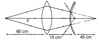
Object O is at 2f of a lens so it will form an image at 2f, i.e. 60 cm from the lens.So the position of an object for a mirror is at (60 - 15)cm = 45cm behind the mirror.
Now from the ray diagram we have
f = +10 cm, u = +45 cm and v = ?
{tex}\frac { 1 } { v } + \frac { 1 } { u } = \frac { 1 } { f } \Rightarrow \frac { 1 } { v } + \frac { 1 } { 45 } = \frac { 1 } { 10 }{/tex}( by using mirror formula)
{tex}\therefore v = + \frac { 90 } { 7 } \mathrm { cm }{/tex} (behind the mirror)
Posted by Ekta Agarwal 5 years, 10 months ago
- 3 answers
Posted by The Poetic Flow 6 years, 8 months ago
- 2 answers
Řøhăň Řąjpůť ✌️✊ 6 years, 8 months ago
Řøhăň Řąjpůť ✌️✊ 6 years, 8 months ago
Posted by Subham Sahu 6 years, 8 months ago
- 0 answers
Posted by Taanya Raj 6 years, 8 months ago
- 0 answers
Posted by Misba Saniya 6 years, 8 months ago
- 1 answers
Sia ? 6 years, 8 months ago
Circuit diagram of n-p-n transistor amplifier in CE configuration is given below:
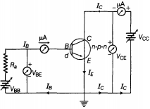
The transistor must be operated close to the centre of its active region.
Posted by Manya Srivastava 6 years, 8 months ago
- 1 answers
Sia ? 6 years, 8 months ago
Electron mobility of a conductor, {tex}\mu = \frac{{e\tau }}{m}{/tex} and {tex}\tau \propto T{/tex}
When the temperature of the conductor increases, the relaxation time {tex}\tau {/tex} of free electrons increases. So mobility {tex}\mu{/tex} increases.
Posted by Nisha Choudhary 6 years, 8 months ago
- 0 answers
Posted by Deeksha Chaudhary 6 years, 8 months ago
- 2 answers
Sia ? 6 years, 8 months ago
-
- Ohmic material
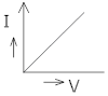
- Non-ohmic material

- Ohmic material
- Example of ohmic material - Copper, Nichrome etc.
Example of Non-ohmic material –Diode, Transistor made of semi-conductors like silicon, germanium etc.
Posted by Pranjal Patel 6 years, 8 months ago
- 0 answers
Posted by Sneha Jain 6 years, 8 months ago
- 6 answers
꧁≪Mämƭå ℭℏᑌĎℎàℜÿ? 6 years, 8 months ago
Řøhăň Řąjpůť ✌️✊ 6 years, 8 months ago
Robin Rajput 6 years, 8 months ago
Posted by Sweta Kumar 6 years, 8 months ago
- 1 answers
Sia ? 6 years, 8 months ago
The whole charge is transferred to the outer sphere.
Therefore, Heat generated = Ui - Uf
{tex}H = \frac { q ^ { 2 } } { 2 C _ { 1 } } - \frac { q ^ { 2 } } { 2 C _ { 2 } }{/tex}
Here, C1 = {tex}4 \pi \varepsilon _ { 0 } R _ { 1 }{/tex}
and C2 = {tex}4 \pi \varepsilon _ { 0 } R _ { 2}{/tex}
{tex}\therefore H = \frac { q ^ { 2 } } { 8 \pi \varepsilon _ { 0 } } \left( \frac { R _ { 2 } - R _ { 1 } } { R _ { 1 } R _ { 2 } } \right){/tex}
{tex}= \frac { \left( 20 \times 10 ^ { - 6 } \right) ^ { 2 } \left( 9 \times 10 ^ { 9 } \right) ( 0.1 ) } { ( 2 ) ( 0.1 ) ( 0.2 ) } = 9 J{/tex}
Posted by Khushi Baranwal 6 years, 8 months ago
- 1 answers
Sia ? 4 years, 8 months ago
Given:
- Capacitance of a parallel plate
- Distance between the plates
- Voltage
- Thickness of slab
- Dielectric constant
To Find:
(i) final charge on each plate
(ii) finial potential difference between the plates
(iii) final energy is the capacitor
Solution:
Capacitance is given by
When dielectric slab constant is introduced
Capacitance is given by
putting the value of
Now,
(i) final charge on each plate
Thus, the final charge
(ii) finial potential difference between the plates
After charging the battery we removed the battery so the charge will remains same
(iii) final energy is the capacitor
Thus, Final energy of the capacitor
Posted by Priyanka Singh 6 years, 8 months ago
- 0 answers
Posted by Sarla Satnam 6 years, 8 months ago
- 0 answers
Posted by Virendra Kumar 6 years, 8 months ago
- 4 answers
Paras Kundu 6 years, 8 months ago
Priya Dharshini ? 6 years, 8 months ago
Posted by Rashi Srivastava 6 years, 8 months ago
- 2 answers
Posted by Rahul Yadav 6 years, 8 months ago
- 2 answers
Sia ? 6 years, 8 months ago
The material of wire used in meter bridge is made of manganin or eureka due to there high specific resistance or resistivity.
Posted by Padma Yangjor 6 years, 8 months ago
- 2 answers
Padma Yangjor 6 years, 8 months ago
Nasima Khan 6 years, 8 months ago
Posted by Jatin Agrawal 6 years, 8 months ago
- 3 answers
Yogita Ingle 6 years, 8 months ago
The rate of change of velocity is known as acceleration.
it's SI unit is m\sec2 .
acceleration = final velocity-initial velocity' time taken
Posted by Aastha Tiwari 6 years, 8 months ago
- 0 answers
Posted by Sumit Singh 6 years, 8 months ago
- 1 answers
Yogita Ingle 6 years, 8 months ago
Field lines are the path of small positive test charge. The charge is moving continuously from point to point rather than jumping from one point to another and experiences continuous force in the electrostatic field. The force experienced or the path followed by charge cannot be discontinuous and hence the lines are not broken. Also, electrostatic field lines represent the electric field strenth and the strength of field is never broken.

myCBSEguide
Trusted by 1 Crore+ Students

Test Generator
Create papers online. It's FREE.
![]()
CUET Mock Tests
75,000+ questions to practice only on myCBSEguide app